Summary of requirements
The following works require ordinary watercourse consent from the Lead Local Flood Authority (Devon County Council) under Section 23 of the Land Drainage Act 1991:
- a) erect any mill dam, weir or other like obstruction to the flow of any ordinary watercourse or raise or otherwise alter any such obstruction; or
- b) erect a culvert in an ordinary watercourse, or
- c) alter a culvert in a manner that would be likely to affect the flow of an ordinary watercourse.
Devon’s Local Policy
Headwalls on watercourses, other than main rivers, do not necessarily require land drainage consent, unless they are constructed in a way that causes an obstruction to the flow. When they represent an obstruction to flow, they become an issue for enforcement rather than consenting.
We recommend that you submit details of your headwall design and in most cases will ask that you apply for land drainage consent for the temporary aspect of the works, whilst ensuring that the permanent structure is suitably designed to ensure that pipe outfalls:
- function correctly;
- are appropriately sited to ensure minimal adverse effects on the recipient watercourse, in particular the stability of its banks;
- are of an appropriate environmentally sensitive and sustainable construction;
- satisfy basic engineering requirements, such as structural integrity and durability;
- are designed for the particular location
Design Summary
- The headwall and wingwalls must neither project beyond nor above the profile of the bank. The design of outfalls must be as visually unobtrusive as possible. If a headwall is designed to set back from the channel no Land Drainage consent is required.
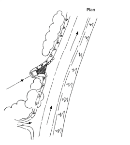
- Wherever possible, outfalls must be located on straight reaches and avoid meander bends; discharge downstream of bridges and culverts; be located to avoid disturbance to flood defence assets, existing trees and their roots, scrub areas, sites or species of conservation interest, wetlands and features of landscape, geological, heritage or archaeological value.
- The outfall pipe must discharge pointing downstream obliquely to the watercourse flow between 30° and 60° (ideally 45 degrees to the direction of flow).
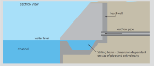
- The footing of the outfall structure must go down at least 600mm below the hard bed of the watercourse, with an additional allowance for scour where this occurs. For ‘tide locked’ and ‘perched’ watercourses, the applicant should contact the FRM team for bespoke advice.
- Anti-scour protection and/or energy dissipaters may be required for the watercourse bed and/or banks. The applicant should demonstrate the need for additional works as required for the headwall. If required, they should be visually unobtrusive and appropriate to the location. Where the discharge velocity exceeds 1.2 m/s, additional controls made be required within the upstream drainage network to control velocities. Where additional works within the channel are required, Land Drainage Consent may be required.
- We would discourage screens or grilles on outfalls unless there are exceptional circumstances (i.e. safety reasons). The applicant should discuss the need for any screening with the relevant drainage authority or adopting authority.
- When handrails are considered necessary for reasons of safety, their design must minimise the risk of obstruction to flood flows and the trapping of debris.
- Where appropriate, flap valves or tidal flaps may be fitted. The applicant will be required to set in place procedures for their regular inspection and maintenance and should discuss the need with the relevant drainage authority or adopting authority.
- The visual impact of the finished structure is an important consideration and construction materials should have regard for the local environment. Consult with the appropriate authority, such as a local authority, before works proceed to ensure that there is no impact on sites and species of conservation interest, geology, archaeology, heritage or landscape. Also consider and include geomorphology, in terms of how appropriate the material is.
- When an outfall pipe passes through a flood defence structure, such as a flood bank, the applicant should seek the permission of the relevant asset owner.
- Where outfall pipes passing through a site of conservation, geological, heritage, landscape or archaeological interest the applicant should seek permission of the relevant authority, such as local authority ecologists or Natural England, to ensure that the selected route is appropriate.
- Where sampling is required due to the nature of the discharge from the headwall, the applicant is advised to discuss any design requirements with the sampling authority, such as the Environment Agency.
Typical details below are meant as an illustration of the LLFA’s general recommendations. They are not to be misconstrued as the only design acceptable, each outfall must satisfy basic engineering requirements, but also be designed for the particular application and locality.
High Velocities
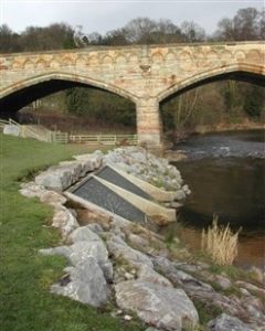
Outfalls with high velocities will require some form of erosion control to minimise scour to the outfall structure. For example, Figure 3, shows a stilling basin, which must be designed to suit the discharge and site conditions.
Integrated Solution
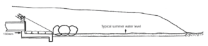
- An integrated solution is set back from the watercourse channel, suitable for low velocity clean water discharges, such as those from a Sustainable Drainage System (SuDS).
- Where possible, the outfall from a SuDS system should be open, such as a swale or linear wetland. This means it is less likely to block, although the outfall location should be made visible in case of any future maintenance required.
- If a piped outfall is necessary, it should finish some distance from the outfall of the watercourse to provide a surface discharge route and more natural discharge in to the watercourse through a set back channel or wetland. (SEPA Guidance [1])

This is a supporting document to Devon’s Local Flood Risk Management Strategy and should be seen as a live document to be updated as new best practice, grants and schemes become available.
We welcome comments from land owners and farmers on best practice and any case studies you would like to share. Please contact Devon County Council Flood Risk Management at floodrisk@devon.gov.uk.
[1] SEPA Engineering in the Water Environment Good Practice Guide, Intakes and Outfalls