Contents
1. Introduction
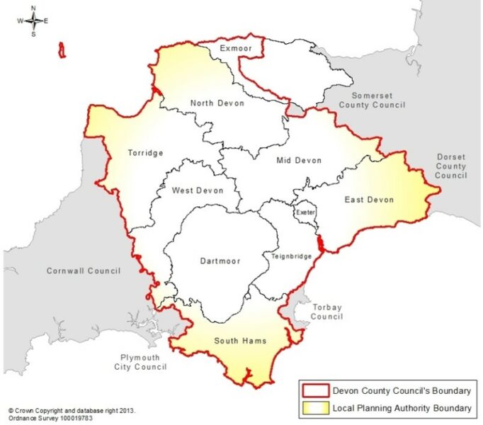
Devon County Council (DCC) is the Lead Local Flood Authority (LLFA) for its administrative area (Figure 1), as defined in the Flood and Water Management Act (2010). This legislation clearly sets out the responsibilities which include managing local flood risk from surface water and groundwater and consenting and enforcement on ordinary watercourses.
In accordance with the Development Management Procedure Order (2015), DCC became the statutory consultee for all major planning applications within its area on 6th April 2015. The advice given is based on various statutory, non-statutory and industry best-practice guidance documents in accordance with the principles of Sustainable Drainage Systems (SuDS).
Consequently, this Guidance does not attempt to rewrite existing documents; it provides a summary of relevant information and signposts the reader to useful documents, whilst providing a local context. This Guidance is therefore intended for use by applicants, developers, architects, engineers and other professionals alike who are seeking advice on the standards required by this LLFA when reviewing planning applications.
2. Legislative and policy background
The National Standards for Sustainable Drainage Systems (2025) provide guidance for the design of surface water drainage in new development, establishing a principles-led “SuDS approach” for managing predominantly clean surface water runoff on greenfield and brownfield sites.
They comprise a runoff hierarchy and a set of minimum design standards (covering flood risk, water quality, amenity, biodiversity, and maintenance) which must be applied together to deliver multifunctional and sustainable drainage systems, with any departures justified and agreed with the approving body. National standards for sustainable drainage systems (SuDS) – GOV.UK
The Environment Act (2021) is the UK’s new framework for environmental protection post Brexit. It provides the government with powers to set new binding targets in relation to water, air quality, biodiversity and waste.
The Flood and Water Management Act (2010) was introduced in response to the concerns raised in the Pitt Review (2008) following the floods across the United Kingdom in 2007. The Act established the LLFAs who are responsible for coordinating local flood risk management within their areas.
The National Flood and Coastal Erosion Risk Management Strategy (2020) was published by the Environment Agency and describes what needs to be done by all Risk Management Authorities involved in flood risk management for the benefit of people and places. The Strategy seeks to better manage the risks and consequences of flooding from: rivers, the sea, reservoirs, ordinary watercourses, sewers, groundwater and surface water. Importantly, the Strategy recommends the use of SuDS on development sites to manage surface water flood risk. The Strategy sets out a vision for a nation ready for, and resilient to, flooding and coastal change today, tomorrow and to the year 2100.
The National Planning Policy Framework (2012 as amended 2021) states that developments should give priority to the use of SuDS in order to ensure that surface water flood risk is not increased. Consequently, all planning applications must be accompanied by a surface water drainage management plan which demonstrates how the surface water runoff from the proposed development will be managed and disposed of, in a manner that does not increase flood risk elsewhere, in accordance with the principles of SuDS.
Devon County Council’s Local Flood Risk Management Strategy (2021-2027) specifically focuses on local flood issues in Devon. Importantly, the Strategy recommends that all new developments should have an effective and robust surface water drainage management system, designed in accordance with the most recent SuDS principles, with the aim of reducing on-site flood risk, whilst also avoiding increasing flood risk elsewhere.
The National Planning Practice Guidance (2014) (as amended 2022) contains a Flood Risk and Coastal Change section which advises on how the planning and design process can take account of the risks associated with flooding and coastal change. It also advises the district councils to consult the LLFA on surface water drainage. It adds that sustainable drainage systems should be provided on every major application unless inappropriate to do so.
The Non-Statutory Technical Standards for Sustainable Drainage Systems (2015) outline the basic principles of sustainable drainage focusing on the water quantity aspect.
The Devon Green Infrastructure Strategy (2015)
In response to the Climate Emergency, the Devon Carbon Plan sets out how Devon will reach net-zero emissions by 2050 at the latest. It recognises that some actions not only reduce emissions of greenhouse gases but may also help to reduce flood risk. For instance, vegetation as part of developments can aid building energy efficiency, both by providing a wind break in winter and in summer vegetation may reduce the overheating of nearby buildings by providing shade and evapotranspiration. Vegetation in SuDS can also contribute to natural carbon storage which is recognised as an important part of achieving net-zero in the Devon Carbon Plan.
Strategic Flood Risk Assessments give information about flooding from all sources within each district council area including the cumulative impact development can have on flood risk and the effect of climate change on risk.
3. What are SuDS?
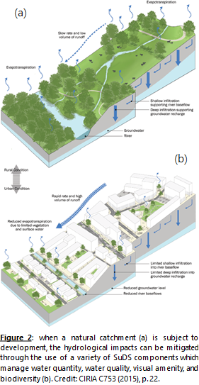
When rain falls on greenfield sites, the water may be intercepted by vegetation, evaporate, infiltrate into the ground, or flow overland to enter water bodies (Figure 2a). However, the way in which these sites hydrologically respond to rainfall is significantly modified when they are developed. Most notably, the introduction of impermeable surfaces results in a significant increase in the rates and volumes of surface water runoff from such sites (Figure 2b).
Traditionally, this surface water runoff has been managed in subterranean piped systems which are designed to prevent localised flooding by conveying surface water runoff downstream as rapidly as possible. An inherent disadvantage of these systems is the risk of downstream flooding resulting from the concentration of flows within a confined area, and the absence of control measures to manage exceedance events. Furthermore, sediment-associated pollutants and contaminants are not naturally managed within these traditional drainage systems, and nor do they provide aesthetically-pleasing visual amenity or biodiversity benefits.
Generally, the use of a variety of above-ground SuDS components, which manage rainfall close to where it falls, provide the greatest environmental benefits, and often cost less than traditional piped systems.
An early assessment of a proposed development site is essential to identify what can and cannot be accommodated within the proposed layout, in addition to any environmental constraints which may preclude the use of particular SuDS components. Drainage engineers must therefore work alongside architects and landscape architects to identify a range of SuDS components, such as those outlined below, which together will provide a surface water drainage management system which comprehensively addresses water quantity, water quality, visual amenity and biodiversity issues.
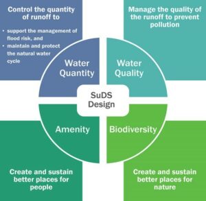
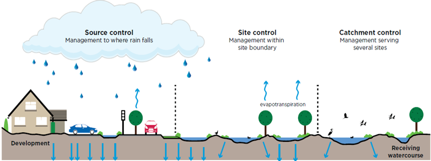
Sustainable drainage systems (SuDS) manage surface water on, or as close as practically possible to, the ground surface in a way that mimics natural hydrological processes. Managing surface water in this way controls the rate and quantity of surface water runoff, improves its quality, and also provides visual amenity and biodiversity benefits (Figure 3).
Generally, the use of a variety of above-ground SuDS components, which manage rainfall close to where it falls, provide the greatest environmental benefits, and often cost less than traditional piped systems. This contrasts with the traditional hard engineering approach which routes the runoff away as quickly as possible using underground pipes.
4. General requirements for SuDS in Devon
4.1 Prioritising Above-Ground SuDS
SuDS Principle 1 – Above Ground SuDS: Devon County Council’s Flood and Coastal Risk Management Team do not consider underground attenuation systems to be truly sustainable components within surface water drainage management systems because they do not provide water quality, amenity or biodiversity benefits. Surface water drainage strategies should make use of above ground sustainable drainage systems.
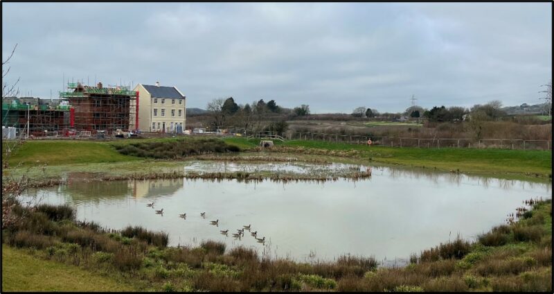
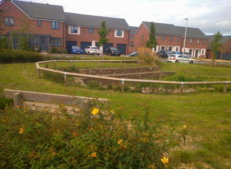
An example of this is one of the numerous attenuation basins at Sherford in Figure 4 below.
4.1.1 Solutions for Above Ground SuDS at constrained sites
Even for constrained sites it is almost always feasible to include some above ground SUDS into the surface water drainage network. Please see Table 1 below for solutions to typical constraints found on sites in Devon.
| Constraint | Solution |
| There is limited space | SuDS should be considered early on in the master planning process to ensure sufficient space is set aside for above ground SuDS forming a treatment train.
Integrating multi-functional SuDS for example as part of the car parking either via permeable paving or rain gardens which can be designed flexibly, can help with reducing the required land take. |
| The site is too steep | Swales can be designed along contours with check dams to provide attenuation and conveyance. Sustainable drainage systems designed in a staggered arrangement for example cascading basins. |
| The site is too flat | Manage surface water close to its source and on the surface for example permeable paving or swales |
| Root Protection Areas | Root barrier protection can be used to prevent damage to pipework whilst protecting the health of trees. |
| High groundwater | An impermeable liner such as waterproof membrane or compacted clay can be used to line above ground SuDS.
In some instances, shallow SuDS can be used such as permeable paving |
| Health and safety concerns | Often above grounds SuDs which have a permanent body of water are seen as a health and safety concern. With appropriate design these risks can be reduced if components are visible and integrated into the local spaces. For example, the maximum slope of a bank for basins and swales should be no more than 1 in 3 and areas of deepest water should be located away from the edge. |
Table 1: Solutions to Utilise SuDS on constrained sites
Underground attenuation systems will therefore only be permitted once robust evidence has been submitted which demonstrates that it is not viable to incorporate any above-ground SuDS components into the surface water drainage management plan. This evidence should be in the form of written statements which clearly justify the necessity to provide underground components, accompanied by sketches, drawings, or constraint plans, where the LLFA deems it necessary.
4.2 Providing a SuDS Management Train
SuDS Principle 2: SuDS Management Train & Water Quality Assessment – DCC Flood & Coastal Risk Management Team require the use of a series of SuDS features acting as a treatment or management train to treat the runoff from a development. Water quality should be assessed using the simple index approach outlined below using the pollution hazard rating and the SuDS mitigation indices.
The SuDS Management Train (Figure 3) describes the use of a sequence of SuDS components across a development site to control the rate and volume of surface water runoff, reduce the concentrations of sediment-associated pollutants and contaminants to acceptable levels, and provide visual amenity and biodiversity benefits. This method ensures that natural hydrological processes are mimicked by managing surface water runoff at source (i.e. close to where the rain falls), with residual flows conveyed downstream to larger SuDS components.
The SuDS Mitigation Indices offers a simple approach, see section 4.2.1 below, to ensure that a SuDS strategy meets the required standard in terms of assessing water quality. DCC LLFA require that the surface water drainage strategies should assess the water quality aspects of their design in line with this approach.
- Prevention: good housekeeping and site design should be employed to manage and reduce surface water runoff and pollution;
- Source control: rainfall should be managed in above-ground SuDS components as close as possible to where it falls to the ground surface;
- Site control: residual flows from source control components should be managed in larger above-ground SuDS components;
- Regional control: surface water runoff from several sites can be managed downstream in large above-ground SuDS components.
Devon County Council’s Flood and Coastal Risk Management Team therefore requires all new surface water drainage management systems to provide a comprehensive SuDS Management Train. These systems should ensure that a development site’s surface water runoff is passed between a variety of source control, and site control, SuDS components, rather than being directly conveyed to one concentrated point (e.g. to one large attenuation pond). Please see Section 4.3 for further information on the water quality aspects of SuDS.
4.2.1 Water quality
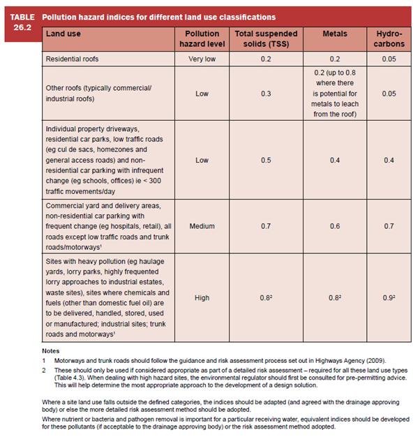
In line with the 4 pillars of SuDS, we require that runoff is assessed in line with the SuDS mitigation indices outlined in the SuDS Manual (C753). This ensures that there is no detrimental impact on the water quality of the runoff post development. Table 26.2 and Table 26.3 of the SuDS Manual, replicated as Figure 6 and 7 below, outline a method for determining the level of treatment provided by certain SuDS features. This method is termed the Simple Index Approach and requires the designer to assess the Pollution Hazard Indices assigned to their type of development as indicated in Figure 5 above.
The designer then reviews the Mitigation Indices for SuDS features and chooses features which will match or surpass the Pollution Hazard Indices.
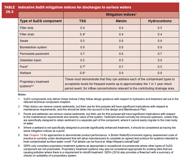
If more than 1 SuDS feature is required to mitigate the Pollution Hazard Indices, then the Mitigation Indices of any feature downstream of the initial feature needs to be divided by 2 (as the surface water draining in will already have had some treatment).

The SuDS Manual (C753) determines mitigation indices for infiltration features separately. This approach should be applied for every surface water management strategy to fulfill the treatment train approach.
4.3 Integrating SuDS into green infrastructure
The use of SuDS presents an important opportunity to improve both urban and rural environments and helps to meet the growing demands to deliver green infrastructure by creating open green spaces which encourage habitat creation. Above ground components can significantly contribute to creating and maintaining biodiversity, in addition to providing public amenity, public health, education, and economic benefits.
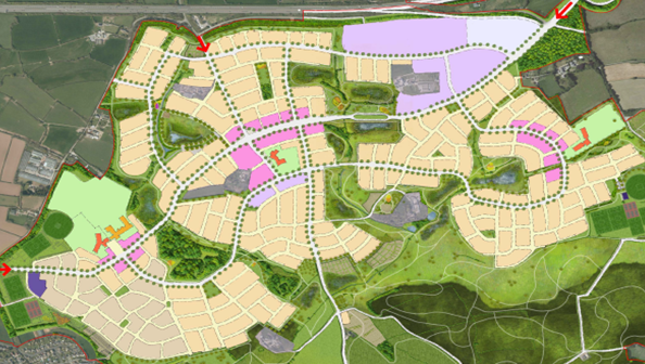
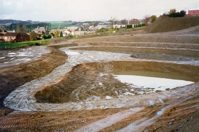
It is therefore essential to consider SuDS as part of an integral part of the broad network of green infrastructure on developments, rather than stand-alone, bolt-on features. An example of this in Devon is the use of two green wildlife corridors at Sherford New Town near Plymouth which boast a series of 14 attenuation basins. These corridors are also important flight paths for protected bats. The green wedges are illustrated in Figure 8 below showing the masterplan for Sherford.
Devon County Council’s Flood and Coastal Risk Management Team therefore strongly advises drainage engineers to work alongside architects, green infrastructure officers, ecologists and landscape architects when designing surface water drainage management systems. A multidisciplinary approach ensures maximum benefits for wildlife and the environment. This collaborative working will ensure that SuDS will not only provide flood risk benefits; they will be fully integrated into green infrastructure networks and contribute to safeguarding the local landscape character and distinctiveness.
Another example shows the use of a volleyball court within a SuDS basin in Austin, Texas see Figure 8 below.
5. Technical requirements for SuDS in Devon
5.1 Technical documents
Devon County Council’s Flood and Coastal Risk Management Team requires surface water drainage management systems for new developments to be designed in accordance with the following technical documents:
- This Sustainable Drainage Systems: Guidance for Devon document (Version 1.7)
(August, 2022); - DEFRA’s Non-Statutory Technical Standards for Sustainable Drainage Systems (March, 2015);
- Where infiltration is proposed, Building Research Establishment Digest 365 Soakaway Design (2016);
- CIRIA’s SuDS Manual (C753) (2015);
- Code of practice for surface water management for development sites BS8585 (2013);
- The Building Regulations 2010 Drainage and Waste Disposal Approved Document H, HM Government (2015).
5.2 Surface water management hierarchy
SuDs Principle 3: Surface Water Management Hierarchy – DCC Flood & Coastal Risk Management Team require that the surface water management hierarchy is utilised when assessing the options for disposing of surface water from a development. Robust evidence should be submitted when an option is discounted. Infiltration should be fully assessed as the preferred option in the hierarchy.
Where not collected for re-use, surface water runoff should be discharged as high up the hierarchy of discharge solutions as is practicable:
- Discharge into the ground (infiltration);
- Discharge to a surface water body (with written permission from the riparian owner);
- Discharge to a surface water sewer, highway drain, or other drainage system (with written permission from South West Water Ltd., Devon County Council Highways, or the riparian owner, respectively);
- Discharge to a combined sewer (with written permission from South West Water Ltd.).
Discharge into the ground (infiltration) must therefore be explored as the primary method of surface water disposal from all development sites in the first instance. Any application proposing infiltration must have undertaken site specific infiltration testing to BRE365 standard at the representative location and depth of the infiltration features being proposed. When site specific infiltration testing indicates that the underlying ground conditions are feasible for the use of soakaways, we have a requirement for groundwater monitoring to determine the maximum winter groundwater level in line with BRE365 and Ciria SuDS Manual C753. A buffer zone of at least 1.0m is required between the base of the soakaway and the maximum groundwater level. We require groundwater monitoring for as long a period as possible but as an absolute minimum must include the period between November to May to determine the maximum groundwater level over the winter months. Full details of our policy on groundwater monitoring is detailed below.
5.3 Groundwater monitoring policy
SuDs Principle 4: DCC Groundwater Monitoring Policy – In line with BRE365 and the Ciria SuDS Manual C753, when an infiltration-based design is proposed to manage surface water runoff groundwater monitoring is required to ensure that the proposed system will function effectively. Ideally a year’s worth of groundwater monitoring should be undertaken, however, if there are time constraints, we would accept monitoring undertaken between the start of November and the end of May. This is provided that the results clearly indicate that the maximum groundwater level has been achieved and has declined for two consecutive months. Ideally, two readings per month should be undertaken.
The monitoring will determine whether there is the required minimum 1.0 m of unsaturated zone between the maximum recorded groundwater level and the base of the infiltration device. If this is not achievable then the drainage design should switch to an attenuation-based design.
The number and location of boreholes required will depend on the number of infiltration devices and their location on the site.
Boreholes should be drilled to a depth of at least 2m below the base level of the infiltration device. We would be happy to speak to applicants or consultants prior to commencement of groundwater monitoring to help inform the location of the boreholes and wider scope if required.
In certain instances, the use of infiltration can be ruled out; for example if the site has a gradient of 1 in 10 or steeper or if there is contamination present at the site. In these cases, on site infiltration testing is not required.
5.4 Runoff rates
SuDS Principle 5: Calculation of Greenfield Runoff Rates – For developments on greenfield sites, runoff rates post development should never exceed greenfield runoff rates for the same return period event.
Devon County Council’s Flood and Coastal Risk Management Team only accept greenfield runoff rates calculated in accordance with the methodologies outlined in CIRIA’s SuDS Manual (C753). Consequently, only impermeable areas draining into the proposed network should be used in the calculation of runoff rates.
For developments on brownfield sites, peak flow control must still match the greenfield runoff rate. However, if this is robustly demonstrated as being unfeasible, the applicant must work backwards to achieve a betterment, with a surface water runoff rate as close to the greenfield conditions as possible. This should be backed up by evidence in the form of calculations indicating runoff rates for a range of storm durations indicating the betterment provided.
On development sites where the greenfield runoff rates are low, off-site discharge rates must still be as close as possible to the greenfield performance; as well-maintained modern flow control structures can now facilitate the low discharge rates.
5.5 Managing volume control
For developments on greenfield sites, the volume of surface water runoff discharged off-site in the 1 in 100 year, 6 hour rainfall event, must never exceed the greenfield runoff volume for the same event.
For developments on brownfield sites, the volume of surface water runoff discharged off-site must still match the greenfield runoff volume. However, if this is robustly demonstrated as unfeasible, the applicant must work backwards to achieve a betterment, with a surface water runoff volume as close to the greenfield conditions as possible, providing robust evidence of the calculations undertaken.
5.6 Long term storage
SuDS Principle 6 Long Term Storage – Where infiltration is not used to dispose of surface water from a development site, long term storage must be provided to store the additional volume of surface water runoff generated by the increase in impermeable area, which is in addition to the attenuation storage required to address the greenfield runoff rates. The incorporation of long-term storage will ensure that each SuDS component is appropriately sized and must discharge at a rate not exceeding 2 litres/second/hectare or Qbar.
5.7 Discharge into tidal waters
For sites which are discharging directly to tidal waters, there is no requirement for attenuation. However, the drainage network should be assessed for tidal locking. This should be the 200 year tidal water level plus an allowance for climate change for 100 years. Consideration should be given to treating the runoff prior to discharge into tidal waters.
5.8 Managing climate change pressures
The Environment Agency has updated their guidance in May 2022, Flood Risk Assessments: Climate Change Allowances with an interactive map showing the allowances for Devon. The rainfall intensity allowances for Devon have increased. The allowances are not uniform in Devon, they are either 45% or 50% for rainfall intensity, depending on the location so we encourage that this map is checked for every project. The map is found by the following link; Climate change allowances for peak river flow in England (data.gov.uk). Devon County Council’s Flood and Coastal Risk Management Team requires the upper end climate change allowance for the ‘2080s’ epoch to be used when calculating peak rainfall intensity.
5.9 Landscaping of SuDS
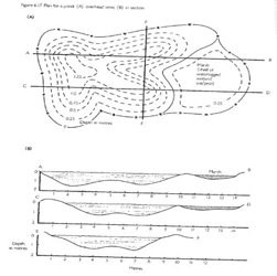
In order to fulfill the 4 pillars of SuDS we require that designers should consider the wider landscape when designing above ground sustainable drainage systems and to achieve maximum benefit from them. We would encourage designers to work with landscape architects to achieve designs which are sympathetic to the natural surroundings. This can include having basins which are structurally varied and with gently sloping side sides of no greater than 1 in 3 and ideally varied side slopes as per Figure 12 below. We also encourage the use of sediment forebays and low flow channels within the basins to manage sedimentation.
5.10 Managing flood risk within the development
SuDs Principle 7: No Flooding For The Design Event – Devon County Council’s Flood and Coastal Risk Management team do not accept any model outputs showing flooding in the design event, being the 100 year event plus the latest allowance for climate change, currently 45% or 50%.
When reviewing model outputs, we do not accept any flooding for the design event, unless it is safely managed in an area specifically designated for the storage of floodwater for example a bunded car park or a landscaped area.
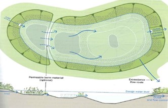
5.11 Exceedance flow routing
From the outset of a project, consideration should be given towards managing exceedance flow routing within the development. These are rare flows above the design standard of 100 year plus the latest allowance for climate change. Flood corridors should be provided for exceedance flows to avoid flows being routed towards private property.
Exceedance events should be designed to safely flow through areas of public open space or green infrastructure and directed towards watercourses. If this is not possible, then flows should be safely directed towards the highway if flows will be able to safely remain within the highway downstream of the site. Site levels may need to be adjusted to achieve the above. Highway kerbs could be designed to direct exceedance flows.
Exceedance events should only be directed through private property (such as gardens) as a last resort. Exceedance Plans should be clearly annotated to illustrate gaps or holes in fences/walls for exceedance routing. There should be no alteration to these boundary treatments in the future. Levels may need to be adjusted within the gardens to ensure that flows are directed correctly. The future homeowners will need to be informed of these exceedance routes.
Dividing development sites into sub-catchments to manage surface water runoff in smaller systems closer to the source of rainfall, in accordance with the SuDS Management Train, will ensure that the surface water drainage management system is more resilient to failure.
5.12 Critical drainage areas
Several Flood Zone 1 areas across Devon have been identified by the Environment Agency as having critical drainage issues. These Critical Drainage Areas (CDAs) have stringent surface water drainage design standards which all new minor and major developments must adhere to:
- The rates and volumes of surface water runoff must be safely managed on-site up to, and including, the 1 in 100 year (+45 /50 % allowance for climate change) rainfall event;
- The rates and volumes of surface water runoff discharged off-site must mimic greenfield performance, up to a maximum of the 1 in 10 year greenfield runoff rate and volume.
To satisfy these standards, additional surface water attenuation storage areas will be required within the development site and contribute to a reduction in downstream flood risk.
There are currently 23 CDAs in Devon; Ashburton, Axminster, Barnstaple (East), Barnstaple (South West), Bideford, Bovey Tracey, Cullompton, Dawlish Warren, East the Water, Feniton, Fremington Yelland, Holbeam, Holsworthy, Ilfracombe and Hele, Ivybridge, Kingsbridge, Modbury, Okehampton, Palmers, Tavistock, Totnes (Bridgetown), Totnes (Warlands) and Whimple. Further information is available on our website; Planning and development – Flood Risk Management (devon.gov.uk).
6. Constructing SuDS in Devon
For all new major developments, a temporary surface water drainage management plan must be submitted to demonstrate how surface water runoff generated during the construction period will be managed. This plan, which may form part of a Construction Environmental Management Plan, must be approved and constructed before any other works are commenced. However, on large sites, phased construction may be requested and the temporary SuDS may be incorporated into the permanent surface water drainage management system.
In addition to surface water runoff, these temporary surface water drainage management systems must also manage any eroded sediment, preventing it from entering the permanent surface water drainage management system during the construction phase (Figure 13). On sites where the use of underground attenuation systems has been approved, this is particularly important because these systems are difficult to comprehensively clean prior to the developer leaving the site, which may compromise the efficiency of the whole system.
The submission of this information is required to ensure that:
- The receiving environment is protected from surface water runoff during the construction phase;
- Each component of the permanent surface water drainage management system is protected from damage during the construction phase;
- The natural infiltration characteristics of the site soils and subsoils are protected;
- A permanent surface water management system where runoff is conveyed and stored, as designed, without causing unacceptable erosion, channelling or sedimentation, is delivered;
- Native vegetation and diverse habitats can be established;
- Appropriate inspections, as required by the relevant authorities during the construction period, can be accommodated.
7. Adopting and maintaining SuDS in Devon
The adoption and maintenance requirements of SuDS components are an important consideration during the design process, and it is the responsibility of developers to put in place suitable arrangements for the lifetime of the development.
There are various options for adoption of SuDS in Devon. The Sewerage Sector Guidance was approved by Ofwat, under its Code for Adoption Agreements, and contains new rules on surface water sewers. Since 1st April 2020, South West Water (SWW) have the ability to adopt certain sustainable drainage systems provided they comply with the criteria outlined in the new Design & Construction Guidance. The decision whether or not to adopt a sustainable drainage feature will lie with SWW. We recommend early consultation with both SWW and ourselves where an application proposes the adoption of sustainable drainage systems by SWW.
A private management company or landowner can also maintain the proposed surface water drainage network often alongside the site’s general landscape maintenance plan.
On occasion, developers may wish Devon County Council, as Highway Authority, to adopt part of a development site’s surface water drainage management system. The decision to adopt these systems is made on a site-by-site basis by Highway Development Management Officers who work outside of the Flood and Coastal Risk Management Team. Nonetheless, the design standard of these systems must at least meet the standards outlined in this Guidance, as well as any other requirements specified by the Highway Authority.
Where surface water drainage management systems are not proposed for adoption by the Highway Authority or South West Water, an operation and maintenance plan and timetable must be submitted to explain:
- What needs maintaining, and the management aims for the site;
- Who will be responsible for maintaining each component part;
- How each component part will be accessed, and the scope of the activities required;
- When each component part needs maintaining.
8. Our role in the planning process
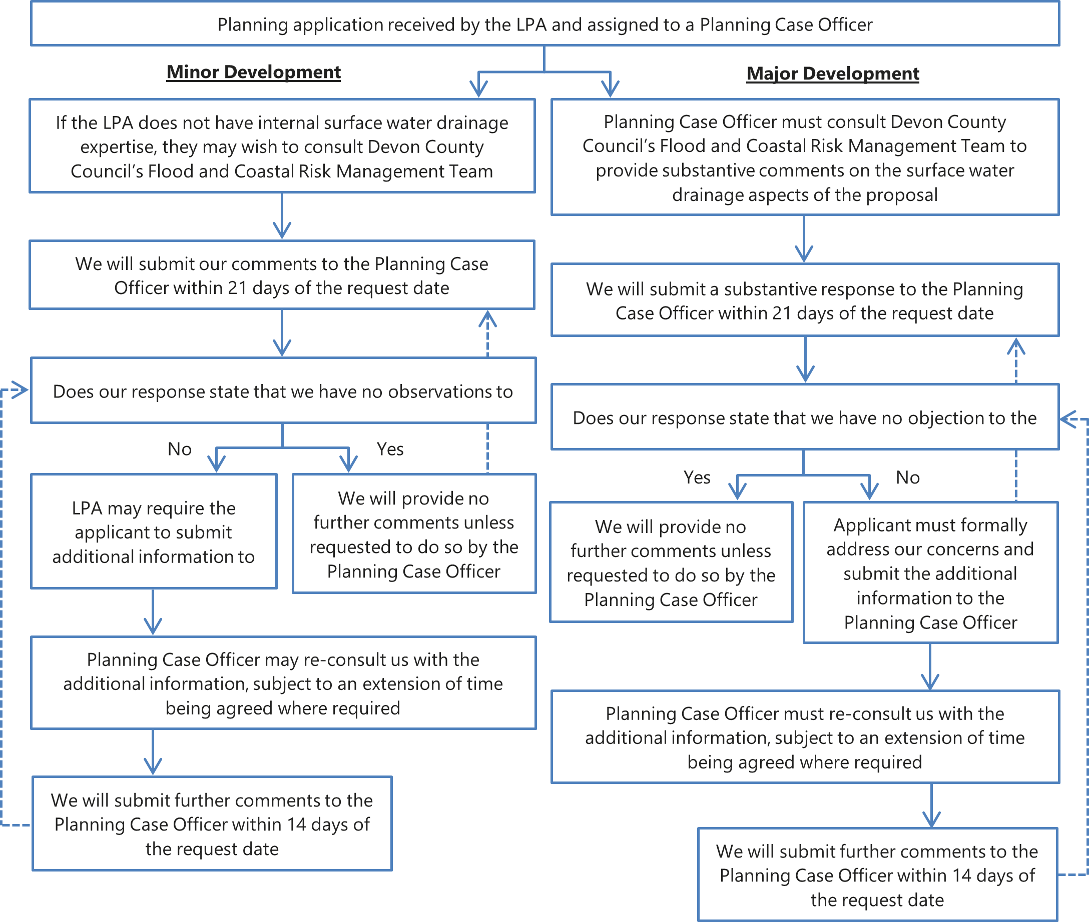
As a statutory consultee in the planning process, it is inherently important that Devon County Council’s Flood and Coastal Risk Management Team ensures that all information concerning the surface water drainage aspects of each planning application under consideration is shared with all concerned parties.
Consequently, if additional surface water drainage information is requested from an applicant, the Flood and Coastal Risk Management Team cannot provide a formal substantive response to the Local Planning Authority until the information has been submitted directly to the Planning Case Officer (Figure 15). This ensures that at all times, the Planning Case Officer is fully aware of any additional surface water drainage information submitted, which may impact other aspects of the application. Once any such additional information is submitted, the Planning Case Officer will be able to formally re-consult the relevant statutory consultees to provide another substantive response, usually within 14 days.
9. Requirements for planning
The surface water drainage management plan for any development site must be considered at the earliest possible stage; we require surface water drainage to be submitted at the outline stage of planning to ensure that sufficient space is set aside for sustainable drainage systems from the outset of any project.
This section identifies our surface water drainage requirements for different stages of the planning process.
9.1 Information required for outline planning applications
- Description of the type of development;
- Location plan at an appropriate scale with a grid reference, showing geographical features, street names, watercourses, or other water bodies in the vicinity;
- Site plan showing the red line boundary and any land under the applicants’ control;
- Site survey showing the existing topography;
- Assessment of all existing flood risks to the site, including from sewer networks, groundwater, overland surface water flows, reservoirs, ponds, canals, and other watercourses;
- Calculations of the current surface water runoff rates and volumes for the site;
- Calculations of the proposed surface water runoff rates and volumes for the site; Please note that calculations based on UK SUDS website are only acceptable for outline applications
- Calculations of the surface water attenuation storage volume required for the
1 in 100 (+45 /50 % allowance for climate change) year rainfall event. This should also incorporate an allowance of 10% for urban creep. This can take the form of Source Control outputs in Micro drainage as an example; - Calculations of the long term storage volume required to store the additional volume of surface water runoff caused by any increase in the site’s impermeable area;
- Evidence that the site has an agreed point of discharge;
- Evidence that the drainage hierarchy has been followed, providing robust evidence as to the viability or otherwise of:
- Discharge into the ground (infiltration);
- Discharge to a surface water body (with written permission from the riparian owner);
- Discharge to a surface water sewer, highway drain, or other drainage system (with written permission from South West Water Ltd., Devon County Council Highways, or the riparian owner, respectively);
- Discharge to a combined sewer (with written permission from the riparian owner).
- Evidence that the capacity of any receiving watercourse is sufficient to receive concentrated flows from the site;
- Explanations of the proposed flood risk mitigation measures;
- Non-technical summary of the proposed surface water drainage management system;
- Plans of the proposed surface water drainage management system, demonstrating that it fits within the proposed site layout, and is practical and sustainable;
- Outline operation and maintenance plan and timetable for the proposed surface water drainage management system over the entire lifetime of the development.
9.2 Information required for a full planning application
- Description of the type of development;
- Location plan at an appropriate scale with a grid reference, showing geographical features, street names, watercourses, or other water bodies in the vicinity;
- Site plan showing the red line boundary and any land under the applicants’ control;
- Detailed site survey showing the existing topography;
- Assessment of all existing flood risks to the site, including from sewer networks, groundwater, overland surface water flows, reservoirs, ponds, canals, and other watercourses;
- Calculations of the current surface water runoff rates and volumes for the site;
- Calculations of the proposed surface water runoff rates and volumes for the site;
- Calculations of the surface water attenuation storage volume required for the
1 in 100 (+45 / 50% allowance for climate change) year rainfall event. This should also incorporate an allowance of 10% for urban creep. This can take the form of Source Control outputs in Micro Drainage for example; - Calculations of the long term storage volume required to store the additional volume of surface water runoff caused by any increase in the site’s impermeable area;
- Evidence that the site has an agreed point of discharge;
- Evidence that the drainage hierarchy has been followed, providing robust explanations as to the viability or otherwise of:
- Discharge into the ground (infiltration);
- Discharge to a surface water body (with written permission from the riparian owner);
- Discharge to a surface water sewer, highway drain, or other drainage system (with written permission from South West Water Ltd., Devon County Council Highways, or the riparian owner, respectively);
- Discharge to a combined sewer (with written permission from the riparian owner).
- Infiltration testing results at the location and depth of each proposed infiltration system;
- Groundwater monitoring in line with our policy on groundwater monitoring detailed in Section 5.3;
- Evidence that the capacity of any receiving watercourse is sufficient to receive concentrated flows from the site;
- Detailed explanations and plans of flood risk mitigation measures;
- Technical summary of the proposed surface water drainage management system;
- Detailed plans of the proposed surface water drainage management system, demonstrating that it fits within the proposed site layout, and is practical and sustainable;
- Detailed exceedance route plans to demonstrate that there is no residual risk of property flooding during events in excess of the return period for which the surface water drainage management system is designed;
- Detailed operation and maintenance plan and timetable for the proposed surface water drainage management system over the entire lifetime of the development;
9.3 Information required for a reserved matters application
- Description of the type of development;
- Location plan at an appropriate scale with a grid reference, showing geographical features, street names, watercourses, or other water bodies in the vicinity;
- Site plan showing the red line boundary and any land under the applicants’ control;
- Detailed site survey showing the existing topography;
- Assessment of all existing flood risks to the site, including from sewer networks, groundwater, overland surface water flows, reservoirs, ponds, canals, and other watercourses;
- Calculations of the current surface water runoff rates and volumes for the site;
- Calculations of the proposed surface water runoff rates and volumes for the site;
- Calculations of the surface water attenuation storage volume required for the
1 in 100 (+45 / 50% allowance for climate change) year rainfall event. This should take the form of a network model including not only the attenuation devices but the wider pipe network too. This should also incorporate an allowance of 10% for urban creep. - Calculations of the long term storage volume required to store the additional volume of surface water runoff caused by any increase in the site’s impermeable area;
- Evidence that the site has an agreed point of discharge;
- Evidence that the hierarchy of drainage solutions has been followed, providing robust explanations as to the viability or otherwise of:
- Discharge into the ground (infiltration);
- Discharge to a surface water body (with written permission from the riparian owner);
- Discharge to a surface water sewer, highway drain, or other drainage system (with written permission from South West Water Ltd., Devon County Council Highways, or the riparian owner, respectively);
- Discharge to a combined sewer (with written permission from the riparian owner).
- Infiltration testing results at the location and depth of each proposed infiltration system;
- Groundwater monitoring in line with our policy on groundwater monitoring detailed in Section 5.3;
- Evidence that the capacity of any receiving watercourse is sufficient to receive concentrated flows from the site;
- Detailed explanations and plans of flood risk mitigation measures;
- Technical summary of the proposed surface water drainage management system;
- Detailed plans of the proposed surface water drainage management system, demonstrating that it fits within the proposed site layout, and is practical and sustainable;
- Detailed exceedance route plans to demonstrate that there is no residual risk of property flooding during events in excess of the return period for which the surface water drainage management system is designed;
- Detailed operation and maintenance plan and timetable for the proposed surface water drainage management system over the entire lifetime of the development;
9.4 Information required for a discharge of conditions application
- Calculations of the surface water attenuation storage volume required for the
1 in 100 (+45/50% allowance for climate change) year rainfall event. This should take the form of a network model including not only the attenuation devices but the wider pipe network too. This should also incorporate an allowance of 10% for urban creep. This should build on work already approved at previous stages of planning. - Calculations of the long term storage volume required to store the additional volume of surface water runoff caused by any increase in the site’s impermeable area;
- Evidence that the site has an agreed point of discharge;
- Evidence that the hierarchy of drainage solutions has been followed, providing robust explanations as to the viability or otherwise of:
- Discharge into the ground (infiltration);
- Discharge to a surface water body (with written permission from the riparian owner);
- Discharge to a surface water sewer, highway drain, or other drainage system (with written permission from South West Water Ltd., Devon County Council Highways, or the riparian owner, respectively);
- Discharge to a combined sewer (with written permission from the riparian owner).
- Infiltration testing results at the location and depth of each proposed infiltration system;
- Groundwater monitoring in line with our policy on groundwater monitoring detailed in Section 5.3;
- Evidence that the capacity of any receiving watercourse is sufficient to receive concentrated flows from the site;
- Detailed explanations and plans of flood risk mitigation measures;
- Technical summary of the proposed surface water drainage management system;
- Detailed plans of the proposed surface water drainage management system, demonstrating that it fits within the proposed site layout, and is practical and sustainable;
- Detailed exceedance route plans to demonstrate that there is no residual risk of property flooding during events in excess of the return period for which the surface water drainage management system is designed;
- Detailed operation and maintenance plan and timetable for the proposed surface water drainage management system over the entire lifetime of the development;
- Information on how silt and runoff is proposed to be managed during construction stage.
10. Existing watercourses
10.1 Existing watercourses at developments sites
Existing watercourses should remain in an open channel, should not be built over and should be integrated within the proposed development. Any culverting of the watercourse should be in line with our culverting policy and should be the minimum required for essential access purposes only. Development should be carefully planned around the watercourse which should encompass a flood free corridor either side of the channel for maintenance access. When discharging into an existing watercourse on site an assessment should be made on the capacity / condition of the watercourse to ensure the watercourse is in an acceptable condition to receive the water.
Any existing watercourses or ditches should not connect into the surface water drainage network including any attenuation features. Maintenance of the watercourse should be included within any site wide maintenance schedule and ownership of the watercourse should be decided at planning stage
11. Land drainage consents & permits
11.1 Works within the vicinity of ordinary watercourses
An Ordinary Watercourse is defined as any watercourse that is not designated as a Main River by the Environment Agency.
In accordance with the Land Drainage Act (1991), if any temporary or permanent works need to take place within such watercourses to facilitate any part of a development (e.g. an access culvert or bridge), Land Drainage Consent must be obtained from Devon County Council’s Flood and Coastal Risk Management Team prior to any works commencing. An online can be obtained from our website.
11.2 Works in the Vicinity of Main Rivers or any Flood/Sea Defence
Applicants must contact the Environment Agency to enquire about, and where necessary apply for, an Environmental Permit for flood risk activities if works are proposed:
- In, under, over or near a Main River (including where the river is in a culvert);
- On or near a flood defence on a Main River;
- In the floodplain of a Main River;
- On or near a sea defence.
12. Frequently Asked Questions
12.1 Design Questions
- Can the developable area be used to calculate the greenfield runoff rates?
No, we only accept the impermeable area within the calculations for the runoff rates. This is in line with the Ciria SuDS Manual and is also required by neighbouring LLFAs in the South West.
- Do you only accept MicroDrainage model outputs?
No, this is not the case. Model outputs from other hydraulic modelling software, such as Causeway’s Flow, are acceptable.
- Do you accept flooding in the design event for the 15 min storm?
No, we do not accept flooding in the design storm event for nay flood events as per Principle 7.
- Can side slopes be less than 1 in 3?
No, the maximum slope of the banks of a basin or swale should be 1 in 3 and we would prefer basins to have varied gradients if possible.
- Can exceedance flows be located within rear gardens?
Exceedance flows should be routed along highways towards car parks or areas of public open space or areas specifically designed to hold exceedance flows. Only if robust evidence is provided would we accept flows through rear gardens as long as there are adequate boundary treatments, a hole in a fence for example, to facilitate this flow routing. This should be clearly marked up on a plan indicating the specific boundary treatments. Flows through rear gardens should be kept to an absolute minimum.
- Is it possible to connect watercourses into surface water drainage systems?
No, watercourses should be kept completely separate to the private surface water drainage. Watercourses should be integrated within the development and not built over.
- Can green roofs be constructed on pitched roofs?
Yes, green roofs can be located on steep roofs. The green roof should contain a storage fleece, a water proofing layer and substrate to store the runoff as well as anti-slip base nettings and sills.
- Can we use 40% for climate change for a new outline application?
No, we only accept climate change allowances which are in line with the latest Environment Agency guidance which is either 45% or 50% for Devon (as per August 2022). Please check for the latest allowances; Flood risk assessments: climate change allowances – GOV.UK (www.gov.uk)
- Do you require sediment forebays in attenuation basins?
We encourage sediment forebays to help the basin achieve the four pillars of SuDS by treating the runoff.
- We plan to use a rain water harvesting tank within the drainage design. Can we therefore avoid any other attenuation?
In line with best practice, rain water harvesting tanks should be modelled assuming they are full to provide worst case scenario therefore additional attenuation will be required.
- Our site is for a commercial development do we still need to factor in an allowance for urban creep?
No, the urban creep requirement is for residential developments only (roof areas) and does not apply to commercial developments or highways.
12.2 Infiltration & Groundwater Monitoring Questions
- Is 4 months worth of groundwater monitoring sufficient?
No, our groundwater monitoring policy states that at least 6 months of monitoring, covering November to May, is the minimum we would accept. This is provided that the results clearly indicate that the groundwater table has peaked and declined for two consecutive months.
- Do we need infiltration testing for an outline application?
No, infiltration testing can be conditioned as long as an alternative attenuated strategy has been submitted with a feasible discharge receptor. Calculations should be provided to back up the design.
- If a neighbouring site has had soakaway testing carried out and the results clearly indicate that infiltration is not a viable option, can we avoid testing on our site?
If you can provide trial pits for your site as well as the neighbouring site which clearly indicate that the underlying geology is the same then no. Please note that the neighbouring site must be immediately adjacent to the site in question. We may seek advice from a geologist on this on a case-by-case basis dependent on the risk downstream.
- Can groundwater monitoring be conditioned?
Yes, if the application is at outline or full stage of planning and if an alternative attenuated strategy has been submitted. This should contain calculations and propose a feasible surface water drainage receptor.
- Can you recommend locations for boreholes on our site for groundwater monitoring?
Yes, if you send us the proposed layout and drainage layout we can recommend locations for monitoring to gain maximum coverage.
- We have undertaken soakaway tests at various locations across the site but not at locations where soakaways are proposed. Do we need further infiltration testing?
Yes, in order for the infiltration testing to be compliant with BRE365 we require infiltration tests at the same location and depth as the infiltration devices being proposed
13. Glossary
Rainwater harvesting systems collect and store surface water runoff from roofs or paved surfaces, prior to use on-site, typically for vegetation irrigation and toilet flushing.
Green roofs are planted soil layers on the roofs of buildings which are irrigated by rainfall and therefore reduce the rate and volume of surface water runoff.
Infiltration systems (including soakaways and basins) collect, store, and dispose of surface water runoff using overlying vegetation, underlying soils, and/or cellular structures.
Filter strips allow surface water runoff to flow across a densely vegetated surface and infiltrate into the ground, whilst also encouraging the natural removal of sediment-associated pollutants and contaminants.
Filter drains allow surface water runoff to be temporarily stored below the surface in a shallow gravel-filled trench, providing attenuation, conveyance and water treatment benefits.
Swales are shallow, open, vegetated channels which are used to convey and treat surface water runoff, whilst also providing a useable public space with biodiversity benefits.
Bioretention systems (including rain gardens) are shallow landscaped depressions which allow surface water runoff to temporarily pond on the surface, before filtering through overlying vegetation and underlying soils prior to collection or infiltration.
Trees can be used within formalised soil-filled pits to complement a range of infiltration SuDS components by collecting, storing and treating surface water runoff by filtration.
Pervious pavements allow surface water runoff to soak through structural paving to enable storage in the sub-base, or infiltration directly into the ground surface.
Attenuation storage systems are below-ground structures which can be used to temporarily store surface water runoff before controlled release or re-use.
Ponds, wetlands and detention basins are features with permanent pools of water, the levels of which increase following rainfall, enabling the attenuation and treatment of surface water runoff.
14. Design Considerations for SuDS Components
14.1 Rainwater Harvesting Systems
- Geotechnical investigation should be undertaken to ensure the suitability of the soils for the foundation of the system, particularly where installation is proposed close to buildings and where groundwater levels are close to the finished ground surface.
- Water butts do not guarantee that storage will always be available unless the system is designed so that any water stored above a set threshold drains slowly to the downstream drainage system;
- Contributing roof area should be calculated in plan because it may not be possible to capture all of the surface water runoff from a roof due to the pitch arrangements;
- Projected water use requirements must be considered when sizing the system.
14.2 Green Roofs
- Hydraulic performance should consider how the roof is likely to behave during extreme storms in both the summer and winter;
- Where the design of the downstream attenuation system is linked to green roof performance, the benefits should be explicitly determined;
- Minimum finished roof fall of 1 in 80, and a maximum of 1 in 3;
- Use a low density growing medium with good water retention, reasonable fertility, mixtures of organic and mineral material, and a depth of between 80-450mm, with variations across the roof area to provide a range of habitats;
- Seed and plug-plant with native drought-tolerant wild flowers of local or UK provenance, with consideration given to shading from other buildings and the orientation to the sun;
- Shallow layer of gravel over a width of 300-400mm from the outside perimeter of the roof to provide vegetation and soil compaction protection;
- Waterproofing layer may need to be anchored to resist wind uplift, be root resistant, and protected from temperature changes and mechanical damage;
- Multiple outlets to reduce the risk of blockages and easily accessible for seasonal cleaning, and separated from the growing medium.
14.3 Infiltration Systems
- Testing must be carried out in accordance with Building Research Establishment Digest 365 Soakaway Design (2016) standards, with test pits draining beyond the 25% effective depth;
- Minimum of 5m away from any building foundation, retaining structure, or highway, unless a suitably qualified geotechnical engineer or engineering geologist can demonstrate otherwise;
- Maximum depth of 3m to enable maintenance, with monitoring points to enable the water level in the system to be observed or measured;
- Base should be flat to provide uniform ponding and infiltration across the surface;
- Base must be at least 1m above the groundwater level to protect the functionality of the infiltration process;
- Fill material should provide >30% of void space;
- Half-drain within a reasonable time (e.g. 24 hours) so that the risk of the system not being able to manage a subsequent rainfall event is minimised;
- System should be of sufficient strength to cater for the loads imposed on them during construction and during their service life;
- Where root intrusion has the potential to be vigorous, root protection barriers should be used.
14.4 Filter Strips
- Strip should extend the entire length of the area being drained;
- Minimum width of 6m;
- Minimum longitudinal slope of 1% to prevent ponding, and a maximum of 5% to prevent erosion;
- Where filter strip slopes are in excess of 5%, a series of level spreaders constructed of durable, non-toxic material graded into the soil can be used to maintain sheet flow;
- Base must be at least 1 metre above the groundwater level to protect the functionality of the infiltration process;
- Time of travel of runoff across the filter strip should be at least 9 minutes;
- Maximum flow velocities should be 1.5 m/s, although this should be lower than 0.3 m/s for effective treatment;
- Where soils are compacted, 300mm of soil should be removed and replaced with a blend of topsoil and sand to promote infiltration and biological growth;
- Use dense, soil-binding, deep routed vegetation (with a salt tolerance where necessary) which should be planted in the spring, and maintained at lengths of 75-150mm to ensure effective filtration performance;
- Where adjacent to a highway or car park, a low-level inconspicuous barrier (e.g. trees, slotted kerbs, or intermittently placed boulders) should be installed to prevent unauthorised vehicular access onto the strip;
- Drop of between 50-100mm from the edge of any hard surface to the filter strip to prevent the formation of a sediment lip.
14.5 Filter Drains
- Longitudinal slope should not exceed 2% because low flow velocities are required for stable conveyance through the filter medium;
- Base must be at least 1 metre above the groundwater level to protect the functionality of the infiltration process;
- Suitable for areas with high groundwater pollution risks when lined;
- Provide an upper sacrificial stone layer to aid in the removal of fine sediments;
- Void ratio and permeability of granular fill should be sufficiently high to allow adequate percolation and to control the risk of blockage;
- Most effective pre-treatment option is for runoff to flow over a small filter strip (~0.5m wide) between the edge of the drained area and the trench;
- Perforated pipe should be provided near the base to collect and convey water to other downstream SuDS components;
- Any lengths of perforated pipes that are more than 10m should be spaced between access sumps so that the pipes can be cleaned by jetting or rodding.
14.6 Swales
- Maximum side slopes of 1 in 3, but 1 in 4 slopes are preferred because this makes maintenance easier, although inaccessible swale edges can have steeper, or even vertical, side slopes;
- Longitudinal slopes should be between 0.5-6%, with check dams being incorporated on slopes greater than 3% (which allows slopes to increase up to 10%);
- Base width of between 0.5-2m to prevent channelling and erosion;
- Normal maximum swale depth is 400-600mm;
- Maximum flow velocities should be 2.0 m/s, although this should be lower than 0.3 m/s for effective treatment;
- Time of travel of runoff along the swale should be at least 9 minutes, or 18 minutes from the top of the swale if there are lateral inflows along its length;
- Half-drain within 24 hours so that the risk of the system not being able to manage a subsequent rainfall event is minimised;
- Use dense, soil-binding, deep routed vegetation (with a salt tolerance where necessary) which should be planted in the spring, and maintained at lengths of 75-150mm to ensure effective filtration performance;
- Where soils are compacted, 300mm of soil should be removed and replaced with a blend of topsoil and sand to promote infiltration and biological growth;
- Underdrains should use a perforated pipe with a minimum diameter of 100mm, with 150mm of clean gravel above the pipe, enclosed in a geotextile fabric.
14.7 Bioretention Systems (Including Raingardens)
- Minimum depth of 400mm for the filter medium and 100mm for the transition layer;
- Surface area of bioretention system should be a minimum of 2% of the overall site area to be drained to the feature;
- Width of system should be greater than 600mm, but less than 20m to ensure easy construction and maintenance;
- Maximum length should be 40m to avoid uneven distribution of water over the surface;
- Permeability of generic soil filter media should be a minimum of 100mm/h;
- Total filter area should not exceed 800m2;
- Maximum depth of attenuated water is 500mm;
- In flow velocities should be 0.5 m/s or 1.5m/s for the 1 in 100 year rainfall event;
- System should half drain within 24 hours to provide adequate capacity for multi-event scenarios;
- Base must be at least 1 metre above the groundwater level to protect the functionality of the infiltration process;
- Batters of side slopes should have a minimum of 200mm of topsoil on them;
- Use a suitable aerated soil to achieve greater than 50mm/hr filtration rates (soil types with more than 65% sand content and a good proportion of humic material work well);
- Dense planting is necessary, with a minimum of 6 plants/m2, which h are tolerant to periodic waterlogging, and pollution from hydrocarbons and icing salt;
- Overflow structure or non-erosive overflow channel should be sized to convey the overflow event.
14.8 Tree Pits
- Species and stock size must be selected to fulfil the intended design function, taking into account the prevailing conditions and ongoing maintenance;
- Select native species, of local or UK provenance, to support wildlife;
- Siting of individual trees must allow sufficient space for the tree crown to grow to a good form;
- Allow a sufficient uncompacted soil volume for healthy establishment (mature canopy spread area multiplied by 0.6m);
- Ensure compacted ground is ripped to relieve compaction prior to the importation of soils into the tree pits;
- Use a suitable soil substrate and avoid placing topsoil lower than 30 centimetres below surface;
- Break up the structure of clay soils through the incorporation of granular and humic material;
- Soils should be 75-80% of maximum dry density;
- Soil permeability should be a minimum of 100mm/h;
- Base must be at least 1 metre above the groundwater level to protect the functionality of the infiltration process;
- Check for potential conflicts with underground services and ensure that utility cables are segregated using ribbed root barriers as appropriate.
14.9 Permeable Paving
- Pervious sub-base to be structurally designed for the site’s purpose;
- Calculations for a range of rainfall duration should be carried out to verify the performance of the available storage volume;
- Outflow from the sub-base should be via a system of perforated pipes or fin drains that provide a large surface area for water to flow into;
- Where slopes are 3% or greater, designers should consider internal terracing or internal check dams in the sub-base to provide a series of compartments;
- Temporary sub-surface storage must provide infiltration and/or controlled discharge;
- Surface infiltration rate should be an order of magnitude greater than the design rainfall intensity;
- Recommended factor of safety of 10 for the surface infiltration rate of all surface types to allow for clogging to affect proportion of the surface water over the pavement design life;
- Geotextile may be specified to provide filtration treatment;
- Lined and underdrained permeable paving can be used when the water table is within 1m of the sub-base, and/or where the site is contaminated;
- Grass reinforcement systems can be used over standard pavement materials, such as open graded, low-fines material;
- To accommodate services, an impermeable central carriageway might be employed to contain services, visually differentiated from pervious parking bays;
- Bedding and jointing material needs to be free-draining and have sufficient durability to resist wear from small movements between blocks.
14.10 Attenuation Storage Systems
- Above-ground SuDS components must be utilised unless the applicant can robustly demonstrate that they are not feasible; even where significant constraints exist, above- and below-ground components can be used in combination;
- Effective upstream treatment is an important consideration to control the risk of the system performance being compromised by sediment accumulation;
- Structural design should be to relevant standards for the appropriate surface loadings;
- Calculations should be carried out to check that the tank will be stable and will not move excessively under the anticipated range of loading conditions during the design life of the tank installation;
- Use an appropriate geomembrane;
- Horizontal water flow may be substantially restricted or even not possible within honeycomb units, so it is highly inadvisable to connect pipes directly to the side of the tank in the form of inlets or outlets;
- Velocity of water entering tanks from larger pipes can be significant, and the internal structure can provide sufficient resistance to cause water to back up in the pipework;
- Groundwater pressure significantly increases the lateral loads on the walls of the tanks, so the base of the system must be installed at least 1 metre above the groundwater level;
- Maintainability of systems needs careful consideration because any failures or blockages will tend not to be noticed, which may increase the site’s flood risk;
- It is vital that it is legally clear who is contractually responsible for both the structural and hydraulic design of a system to remove any confusion about who is legally responsible for the design in situations where failures have occurred.
14.11 Pond & Wetlands
- Permanent pool of water for water quality treatment and temporary storage for flow attenuation;
- At the water surface, a 1 metre wide muddy aquatic bench should be provided for emergency egress;
- Minimum depth for open water areas of 1.2m;
- Maximum depth of water should not normally exceed 2m in the most extreme design event;
- Maximum side slopes of 1 in 3, with shallower side slopes being better for biodiversity;
- Recommended length/width ratio is between 3:1 and 5:1;
- Bottom of basin should be fairly flat, with a slope of no more than 1 in 100 towards the outlet, to maximise contact of runoff with the vegetation;
- For maximum pollutant removal effectiveness, flows should be distributed across the full width of the basin;
- Topography and vegetation should reflect natural forms which fit well with the landscape context, enhancing the character of the area and supporting wildlife;
- Should not follow a geometric profile; they should have edges with curves and undulations to produce an aesthetically interesting and natural-looking feature;
- Indented shorelines, islands and native vegetation throughout;
- Appropriate access to the pond for maintenance activities, and to all inlets, outlets and control structures;
- Reinforced grass may be required for maintenance routes where vehicular access is anticipated;
- Mowing should ideally retain grass to lengths of 75-150mm across the main treatment surface to assist in filtering pollutants and contaminants and retaining sediments;
- Fencing is not desirable as it will reduce the amenity benefits provided by the pond, provide a barrier to easy maintenance and provide a trap where